When working with the graphics pipeline, the perspective projection is commonly used to give a realistic depiction of a scene, where objects close to the camera appear larger than objects far away. The perspective transformation has the important feature of mapping 3D lines to 3D lines. In this post we will go into why this property is important and give a proof of it.
The reader should have some familiarity with the graphics pipeline and the role the projection transformation plays in it. The Sources section provides good resources on the subject.
Coordinates setup
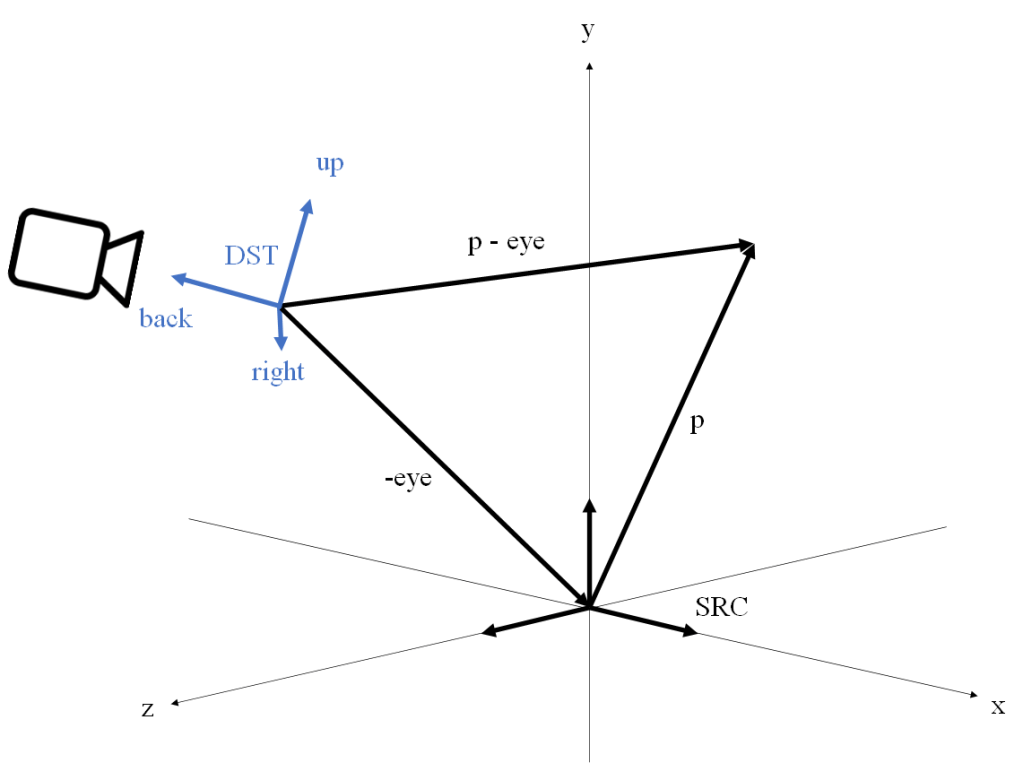
In the following we will assume that our view space is a right-hand coordinate system, has X pointing right from the camera, Y pointing up, and Z pointing back from the camera. This is the traditional setup of the view coordinate system in OpenGL applications.
Within the view space we define our viewing frustum by a near plane orthogonal to the Z axis placed at 


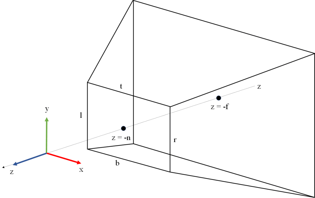
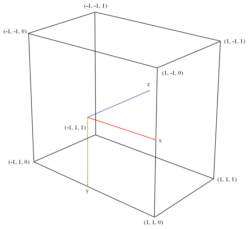
Our NDC (Normalized Device Coordinates) system will be right-handed with X pointing right, Y pointing down, and Z pointing into the screen. The canonical view volume is defined by X and Y ranging from -1 to 1, and Z ranging from 0 to 1. The canonical view volume is illustrated in Figure 2. This NDC setup is how Vulkan defines it in its spec.
Other rendering APIs use different NDC setups. OpenGL defines its NDC as a left-hand coordinate system, with X pointing right, Y pointing up, Z pointing into the screen, and all three coordinates ranging from -1 and 1. DirectX defines its NDC as left-handed, with X pointing right, Y pointing up, Z pointing into the screen, X and Y ranging from -1 to 1 and z ranging from 0 to 1.
We have defined our view coordinate system with the approach usually employed in OpenGL applications. This should be natural for those accustomed to working with this API, and also has the advantage that the Y axis points up allowing us to think of Y as “height”. Note however, that since the Vulkan NDC has Y pointing down and Z pointing in the same direction as the camera, we will need to define our projection transformation with negative coefficients in Y and Z, in order to flip the direction of these axes.
The perspective transformation
With the above coordinates setup (mapping z to the interval [0, 1]) the perspective transformation can be described by the following matrix:

Remember there is an implicit division by w after the matrix is applied. Note also that we have defined the fourth row of the matrix as 


For a detailed derivation of this matrix, see Sources. The explanation in that page is oriented towards the OpenGL NDC system so the matrix they build is different from our Vulkan-oriented matrix, but they show a generic method that can be used to derive the perspective matrix with any NDC setup.
Projection and the graphics pipeline
As a reminder, the following is a simplified summary of the steps of the graphics pipeline in a typical application and the role the projection matrix plays in it. Some details like the orientation of the framebuffer coordinate system vary depending on the graphics API. This summary assumes we are working with Vulkan. For a more detailed description see Sources.
- The model space coordinates of each vertex are input into your vertex shader.
- Your vertex shader takes the model space coordinates of the vertex, converts them to homogenous coordinates by adding a w component with value 1, and multiplies the homogeneous vector by the 4×4 model matrix to obtain the world space coordinates.
- The vertex shader takes the world space coordinates and multiplies them by the view matrix to obtain the view space coordinates.
- The vertex shader takes the view space coordinates and multiplies them by the projection matrix P above to obtain the clip space coordinates. This is what the vertex shader returns. The vertex shader may combine the model, view an projection matrices into a single multiplication and return
.
- The clip space coordinates returned from the vertex shader are divided by their w component to obtain Normalized Device Coordinates (NDC). This step is sometimes called perspective division. This is a fixed function step.
- The NDC are converted to framebuffer space (called window space in OpenGL) with an affine transform. The window space coordinates describe the vertex position in a coordinate system that has its origin in the top left corner of the window, and is scaled so that pixels have width and height 1 . This is a fixed function step.
- Primitives are rasterized (converted to a set of samples called fragments). For each fragment, its barycentric coordinates are computed in framebuffer space, and then its framebuffer space coordinates
are computed by linearly interpolating the framebuffer space coordinates of the primitive vertices, using the barycentric coordinates of the fragment as weights. The framebuffer space z coordinate in particular is relevant because it will be used in the z test. This is a fixed function step.
- The fragment’s vertex attribute values (e.g. texture coordinates) are computed via perspective-correct interpolation of the vertex attributes of the vertices. This involves using the view space (pre-projection) z values at the vertices. This is a fixed function step.
- Early z test: if the driver and GPU support it (most do) and our pipeline doesn’t write to the depth buffer or use
discardin the fragment shader, the pipeline will probably do the early z test at this point. The fragment’s z coordinate in framebuffer space is compared against the value stored in the depth buffer for the current pixel. If the fragment’s z is greater or equal than the value stored in the depth buffer, it means the fragment is occluded so it is discarded. Otherwise, the depth buffer is updated with the framebuffer z value of the fragment and processing of the fragment continues. This is a fixed function step. - Your fragment shader is invoked with the framebuffer space coordinates of the fragment as input.
- If we have a stencil buffer attached, the stencil test is performed.
- If the pipeline wasn’t able to do the early z test, z testing is performed at this point (late z test). Otherwise the late z test is skipped. The late z test involves the same read and possible write of the depth buffer described above in the early z test step.
- The color returned from the fragment shader is written to the framebuffer.
The use of a depth buffer and a stencil buffer is optional in the graphics pipeline, but its use is so common that we have included it in the summary.
The collinearity property
The perspective projection doesn’t preserve parallelism. Parallel lines in view space get mapped to lines that meet in a point, the projection of which over the near plane is called their vanishing point.

Lengths are not preserved either. Points get shifted inwards and backwards towards the far plane, and the farther from the near plane we go the more shifted they are. This generates the effect of far away objects looking smaller than objects of the same size that are closer to the camera.
However, the perspective projection as defined above has the important property that 3D lines in view space (after applying perspective division) get mapped to 3D lines in framebuffer space. Note we are not only talking about lines being mapped to lines in the projection plane: the 3D coordinates post projection also remain aligned, and this is important. For this reason we say that perspective is a projective transformation (it maps lines to lines, without preserving parallelism nor distances).
The key feature of the projection that is the cause of this property is the way the z coordinate is remapped in the third row of the projection matrix. When we look at the perspective matrix, we can see that after w division, the view space coordinates 


Notice how 


The mapping of
Remember that the graphics pipeline needs to determine the value of the framebuffer space z for each fragment, based only on the framebuffer space z values at the vertices of the primitive. This is done by doing a linear interpolation of the framebuffer space z values at the vertices (i.e. a linear combination of the vertices’ z values using the sample’s barycentric coordinates as weights). This is the reason the collinearity property is important: if straight lines in view space were turned into curves after projection, this linear interpolation would be impossible.
Note that here we are talking about the linear interpolation of the framebuffer space z values, which is used in depth testing to discard occluded fragments. This should not be confused with the perspective-correct interpolation of vertex attributes, which is done using the clip space w (which takes the value of the pre-projection view space -z) and is therefore independent of how the projection remaps z.
Formal statement of the collinearity property
For the purposes of stating the collinearity property in formal terms, there is an important observation that will allow us to present the theorem in a more simple and elegant way. Note that the way we have defined the perspective projection can be divided in two steps:
- Dividing input coordinates by
- Multiplying by scalars and adding scalars in order to adjust the ranges and orientations of
The affine component doesn’t affect collinearity (we already know it will map lines to lines due to it being an affine transformation ). In order to prove that perspective maps lines to lines, it’s enough to show that the projective component does. Note that the projective component doesn’t need to flip Y or Z, this is part of the job of the affine component.
Theorem. Let 


Proof
From the definition of


We can separate


If we denote 


Alternative proof
The book “3-D Computer Graphics A Mathematical Introduction with OpenGL” by Samuel Buss provides an alternative proof, with a more generic statement. The proof can be found in chapter II “Transformations and Viewing”. The argument in broad strokes is the following.
Consider any function 


- The image subspace is of dimension 0. Then the function is not defined for the point
- The image subspace is of dimension 1. Then its points represent a point in
- The image subspace is of dimension 2. Then its points represent points in
Sources
- About the derivation of the perspective matrix in OpenGL: https://www.scratchapixel.com/lessons/3d-basic-rendering/perspective-and-orthographic-projection-matrix/projection-matrix-introduction.html
- Stackoverflow answer showing a graphical comparison between linear and hyperbolic mapping of z: https://stackoverflow.com/questions/47801957/linear-depth-buffer/47802596#47802596
- Buss, Samuel R. “3-D Computer Graphics A Mathematical Introduction with OpenGL”. Provides an alternative and more generic proof of the property that perspective maps 3D lines to 3D lines.
- About the rasterization algorithm and linear interpolation of z values: https://www.scratchapixel.com/lessons/3d-basic-rendering/rasterization-practical-implementation/visibility-problem-depth-buffer-depth-interpolation.html
- About perspective-correct interpolation of vertex attributes: https://www.scratchapixel.com/lessons/3d-basic-rendering/rasterization-practical-implementation/perspective-correct-interpolation-vertex-attributes.html
- Low, Kok-Lim. Perspective-Correct Interpolation. This is another in-depth article about the subject: https://www.comp.nus.edu.sg/~lowkl/publications/lowk_persp_interp_techrep.pdf
- Another explanation about perspective-correct interpolation in Stackoverflow: https://stackoverflow.com/questions/24441631/how-exactly-does-opengl-do-perspectively-correct-linear-interpolation
- About the stages of the graphics pipeline: https://www.khronos.org/opengl/wiki/Rendering_Pipeline_Overview
- Wikipedia on projective transformations: https://en.wikipedia.org/wiki/Homography

 vector space and two bases
  and
and  . The function that takes the coordinates of a vector in
  is composed of the coordinates of the vectors of
  can also be obtained as the inverse of the basis change from
 . If we multiply this vector by


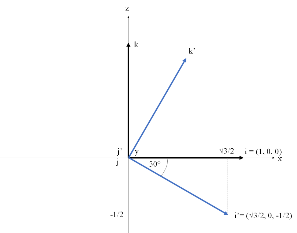
 be a rotation of 30 degrees counterclockwise around the
  axis. The
  in
in ![[i]_{DST}](https://s0.wp.com/latex.php?latex=%5Bi%5D_%7BDST%7D&bg=FFFFFF&fg=181818&s=0&c=20201002) , are
, are  . Figure 1 illustrates this approach. We are using a right-handed coordinate system (Y points into the screen). The vectors of the canonical basis
  , and
, and  , show in black. The rotated vectors of
  ,
,  and
and  , shown in blue (note the
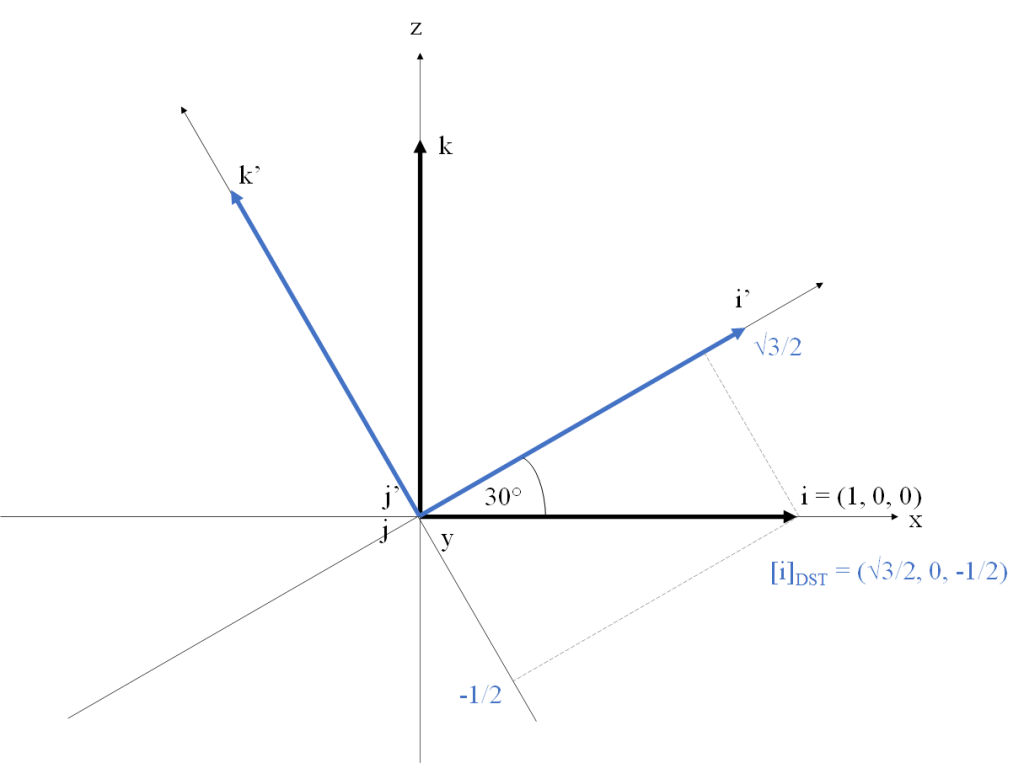
 and a vector
  in
in  .
. .
. of
of  .
. are of length 1. In that case the coefficients becomes simply
  .
. and
and  , a function
  is an affine map if there exists a linear map
  such that
  for all
  in
in  that we call origin and a basis
  for each point
  there is a unique set of coefficients
  such that:
 cannot be described by a 3×3 matrix, because it’s not a linear map (it has a translation component).
 which is a composition of linear map
  (that is
  ),
),  . To compute the matrix
 are taken from the associated matrix of

 by an affine map
  (setting its
  component to 1), compute the matrix-vector multiplication
  , then we convert
  back to
  .
. matrix multiplication maps the object onto its desired position and the frustum into the NDC frustum of the API you are using.
 axis points up, and the
  in world space. Its orientation can be described by an orthonormal basis
  whose vectors are defined in world space and point right, up and back from the camera as their names imply. This defines another affine frame with its origin at
  , and an
  vector indicating which direction is up from the camera, find the matrix
  which defines the camera’s direction. The purpose of
  as the normal to this plane.
 is easy to obtain by subtracing

 as the cross product of them:
 , because the view frame is left-handed. Regardless of how you have chosen the coordinate systems, the procedure from this step onwards is the same regardless.
 such that the displacement vector
  can be obtained as the linear combination
  . So the first thing we need to do is compute the displacement vector
  , and its matrix is:


 is a translation by the vector
  , but this vector is nothing but the coordinates of
  is equivalent to converting the coordinates of the point